


Rigid-flex integration
Rigid sections and flexible tails in one board — eliminating connectors, saving space and boosting reliability.
2–32 layers
Custom flexible circuits for wearables, medical devices, camera modules, and compact interconnects. XinshunPCB supports polyimide material selection, bend-area planning, and connector stiffeners to match your design and assembly requirements.
Request a Flex PCB QuoteExplore construction options, materials, dimensions, circuit features, surface finishes, and test parameters for flexible circuits. Rigid-flex layer counts and thicknesses are listed separately where applicable. Contact us to review the requirements of your specific design.
| Parameter | Specification | |
|---|---|---|
| Layers — flexible | 1–12 layers | |
| Layers — rigid-flex | 2–32 layers | |
| Base material | PI, PET, PEN, FR-4, DuPont (Kapton) | |
| Stiffeners | FR4, aluminum, polyimide, stainless steel | |
| Copper thickness | 1/3 oz – 2 oz | |
| Parameter | Specification | |
|---|---|---|
| Max / min board size | Min 0.2″ × 0.3″ · Max 20.5″ × 13″ (≈ 520 × 330 mm) | |
| Final thickness — flexible | 0.002″ – 0.1″ (0.05 – 2.5 mm) | |
| Final thickness — rigid-flex | 0.0024″ – 0.16″ (0.06 – 4.0 mm) | |
| Insulation thickness | 0.5 – 2 mil (12.7 – 50 µm) | |
| Parameter | Specification | |
|---|---|---|
| Min. trace width / space | 0.5 oz: 4/4 mil · 1 oz: 5/5 mil · 2 oz: 5/7 mil | |
| Min. annular ring | 0.5 oz: 4 mil · 1 oz: 5 mil · 2 oz: 7 mil | |
| Min. hole size | 8 mil | |
| Hole tolerance | PTH ±3 mil · NPTH ±2 mil | |
| Min. slot | 24 × 35 mil (0.6 × 0.9 mm) | |
| Parameter | Specification | |
|---|---|---|
| Solder-mask / coverlay alignment tol. | ±3 mil | |
| Silkscreen alignment tol. | ±6 mil | |
| Silkscreen line width | 5 mil | |
| Finish | Specification | |
|---|---|---|
| Immersion Nickel / Gold (ENIG) | Nickel 100–200 µin · Gold 1–5 µin | |
| Gold plating (electrolytic) | Nickel 100–200 µin · Gold 1–4 µin | |
| Immersion Silver | Silver 6–12 µin | |
| Immersion Tin | Available | |
| OSP | Film 8–20 µin | |
| Parameter | Specification | |
|---|---|---|
| Profile tolerance — accurate / ordinary mould | Accurate mould ±2 mil · Ordinary mould ±4 mil | |
| Profile tolerance — knife mould / hand-cut | Knife mould ±8 mil · Hand-cut ±15 mil | |
| Test voltage | Testing fixture: 50–300 V | |

Send your Gerbers, stackup and bend requirements — our engineers confirm manufacturability against this spec and reply with a quote, usually within 24 hours, plus a free DFM review.
Request a QuoteFrom simple single-layer flex to complex rigid-flex assemblies that bend, shield and survive millions of cycles.
Rigid sections and flexible tails in one board — eliminating connectors, saving space and boosting reliability.
2–32 layers
Multilayer flex with laser microvias and fine lines for dense, high-pin-count flexible interconnects.
Microvia
Bend-to-install or continuous-flex designs engineered with rolled-annealed copper and optimized bend radius.
Millions of cycles
Conductive shielding film over flex circuits for noise-sensitive and high-frequency applications.
Shielded flex
Selective stiffeners and bevelled gold ZIF / contact fingers for connector insertion and component areas.
FR4 · PI · steel
Impedance-controlled flex and rigid-flex with stackup design support and TDR verification.
Microstrip / striplineEvery flexible and rigid-flex board is fabricated, inspected and documented to the relevant industry standards.

Flex & rigid-flex

Flex design spec

Board acceptability

Assembly Class 2/3

Quality management

Listed · 94V-0
EU compliant

Medical-capable

Automotive-capable

Aerospace-capable
Explore PCB and PCBA solutions for applications where flexible interconnects, compact packaging, and reliable connections are essential, from medical devices and connected sensors to industrial and automotive electronics.

Engineered to withstand massive electrical currents, thermal stress, and continuous mechanical vibration. XinshunPCB delivers IPC Class 3 heavy copper boards, high-thermal metal-core solutions, and turnkey SMT assemblies for grid-scale energy storage, industrial robotics, motor drives, and solar inverters.
Explore Solution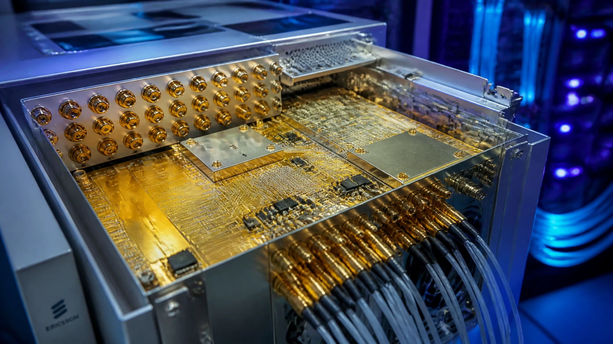
From wireless gateways and connected sensors to networking equipment, XinshunPCB supports custom PCB fabrication and assembly for communication hardware. Align materials, stackups, compact layouts, and production testing with your application, from initial prototypes to repeat production.
Explore Solution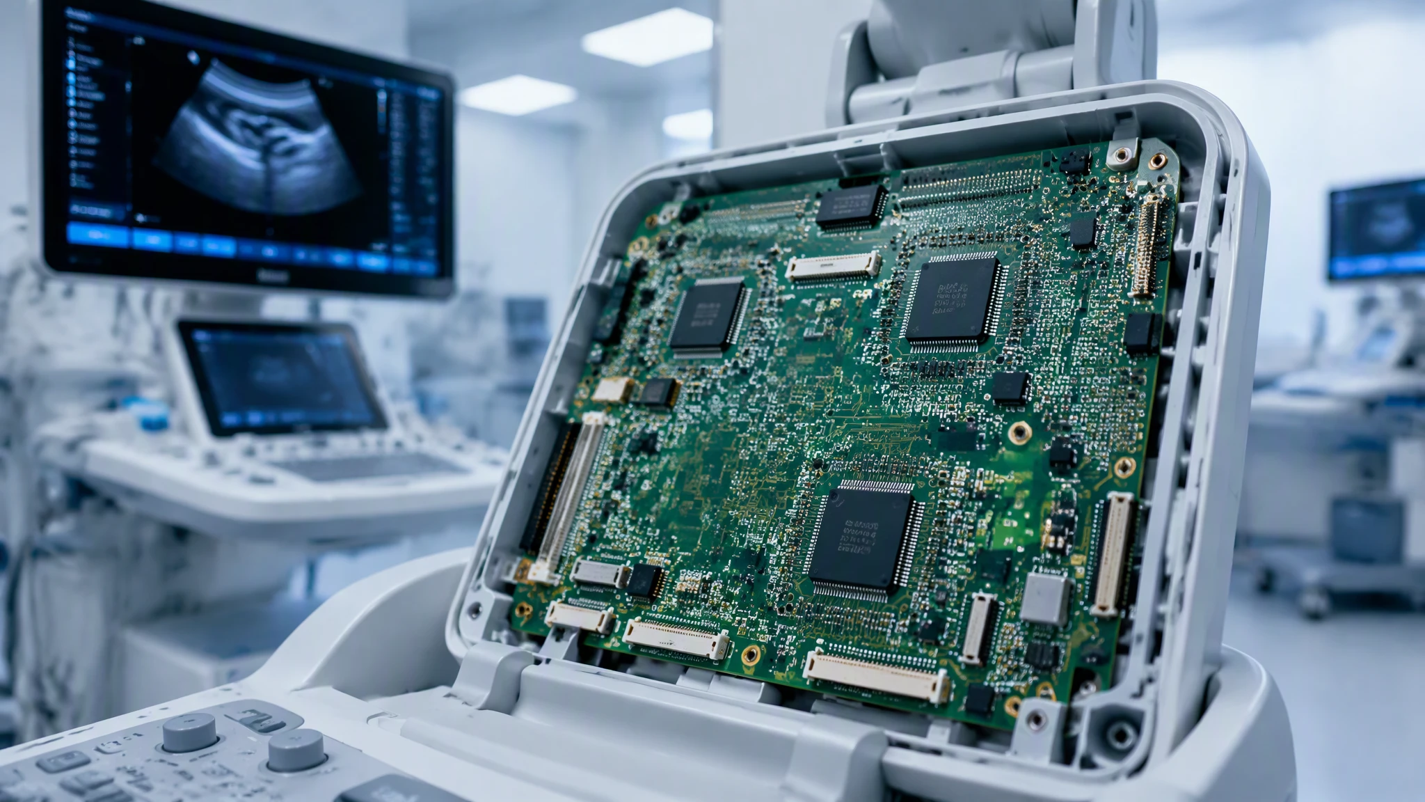
From patient monitoring and diagnostic instruments to medical imaging systems, XinshunPCB provides custom PCB fabrication and PCBA assembly for healthcare equipment. We help you align board materials, circuit layouts, and assembly requirements with your application, supporting development from initial prototypes to production.
Explore Solution
Engineered to withstand extreme mechanical shock, high-voltage switching surges, and thermal cycling from –40°C to +150°C. XinshunPCB delivers IATF 16949-aligned, IPC-A-610 Class 3 turnkey PCB fabrication and SMT assembly for electric vehicle (EV) powertrains, ADAS sensing, high-voltage BMS, and under-hood body control modules.
Explore SolutionFind practical answers about flexible circuit materials, bending requirements, stiffeners, coverlay, inspection, and the files needed for a Flex PCB quotation.

Have a new project or custom PCB requirements? Simply fill in your project details below. XinshunPCB’s FAE engineering team will analyze your specifications and deliver a detailed formal quotation along with free engineering advice within 2–24 hours.

Detailed formal quote & lead time provided within 2-24 hours.

Your contact info and project specs are kept strictly confidential.

Experienced FAE support to help optimize your specifications.
Need a reliable manufacturing partner for your next project? Our global support team is standing by.
Trusted by global integrators for PCB manufacturing, enterprise hardware, and high-reliability deployment solutions.