
Choose Test Coverage Before Comparing Quotes
PCBA testing services should be defined by the defects and operating requirements they address, not by a generic “tested” label. AOI, X-ray inspection, in-circuit test (ICT) and functional test answer different questions. A useful purchasing specification identifies the method, scope, acceptance limits, test access, reporting and responsibility for fixtures before a build is released.
For OEMs and hardware teams, the objective is an agreed release decision for each assembly. Start with the product risks, then choose complementary checks. A board that looks acceptable may still have an electrical fault; a board that boots may still have an untested interface. No single method establishes complete defect coverage or long-term reliability.
Our turnkey PCB assembly services provide the commercial starting point for a project review. This guide explains how to specify the testing portion. For the wider quotation, use the PCBA cost breakdown to separate recurring test time from fixture development and engineering charges.
AOI vs X-Ray vs ICT vs Functional Test
Use this comparison as a planning aid. Actual detection depends on equipment, programming, board access, component technology and the approved test procedure.
| Method | Main purpose | Important limitation | RFQ decision |
|---|---|---|---|
| AOI | Inspect visible placement and solder features | Cannot establish hidden-joint integrity or full electrical behavior | Inspection stage, visible features, criteria and disposition |
| X-ray / AXI | Examine hidden solder geometry, including selected BGA or QFN joints | Image interpretation is not an operating test | Packages, joints, sampling and acceptance criteria |
| ICT | Measure accessible electrical nodes and selected component characteristics | Access and circuit topology constrain coverage | Net coverage, test points, fixture and program |
| Functional test | Exercise defined board functions under specified conditions | Passing only proves the functions and conditions actually tested | Firmware, stimuli, loads, limits and records |
SPI is another process-control step: it evaluates solder-paste deposits before placement and reflow. Keep it distinct from finished-assembly inspection and electrical release testing. Your plan may combine several methods, but each should have a documented purpose rather than being included merely to lengthen a checklist.
AOI and X-Ray: Inspect Different Features
Automated optical inspection (AOI) uses images to check visible assembly features against a programmed reference. Depending on the system and recipe, checks can include missing or misplaced parts, orientation and visible solder geometry. Program setup and review of flagged results matter; a machine indication needs the agreed acceptance decision.
X-ray inspection addresses geometry that cameras cannot see directly, such as joints underneath some packages. OMRON’s technical explanation of AXI describes inspection of visually inaccessible underside solder joints. Specify which devices and joints need evaluation and how images will be assessed. Avoid treating one selected image as proof that every joint on every board was inspected.
Neither inspection method substitutes for an electrical or operating test. Ask whether the quoted scope is every board, selected packages on each board, first-article checks or a defined sample. Record who reviews failures and what happens after rework.
Workmanship requirements also need a contract reference. IPC’s assembly standards overview distinguishes soldering process requirements in J-STD-001 from assembly acceptability in IPC-A-610. State the applicable edition, class and any customer-specific limits. A standard name alone does not define your full test program.
ICT: Electrical Checks Need Design Access
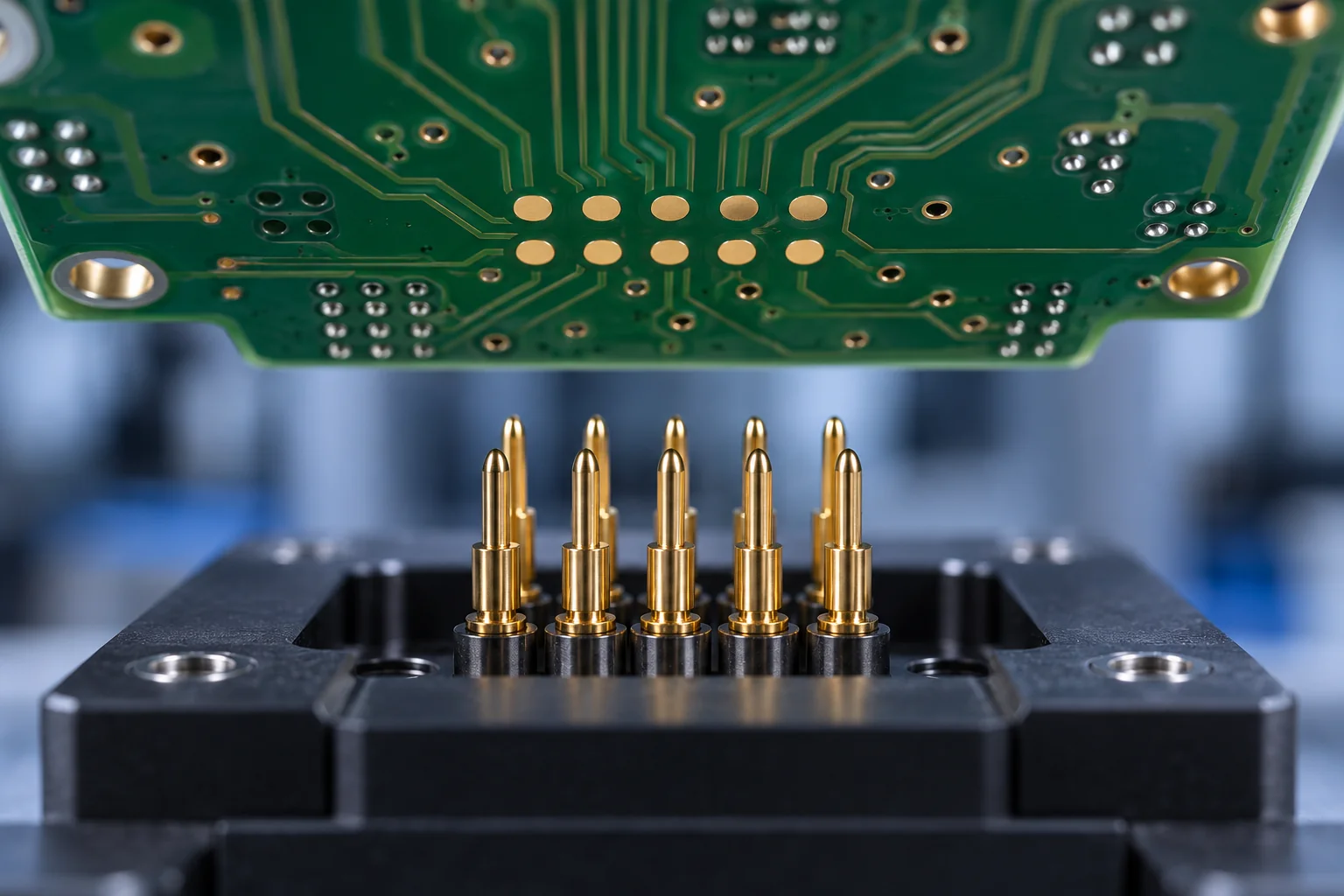
In-circuit test uses electrical access to evaluate the assembled circuit at selected nodes. Shorts, opens and selected component values or characteristics are typical targets. Keysight’s ICT overview contrasts component-level checks with testing the behavior of the complete device. The attainable coverage depends on the specific design and program.
Review test-point availability before layout release. Probe landing areas, spacing, side access, fixture support and clearance around connectors or tall parts can determine whether a node is practically accessible. Circuit paths can affect measurements, so “every component tested” should never be assumed from the presence of an ICT station.
Request an access and coverage report listing targeted nets or fault categories, included checks and exclusions. A percentage is useful only when its denominator is clear. Net access, component coverage and fault coverage describe different things.
For low volume or changing designs, discuss fixture economics and alternative access methods. Flying-probe or boundary-scan approaches may be candidates where the design and equipment support them; they require their own feasibility review. Do not assume they duplicate every ICT measurement or remove the need for functional testing.
Functional Test: Define What Passing Means
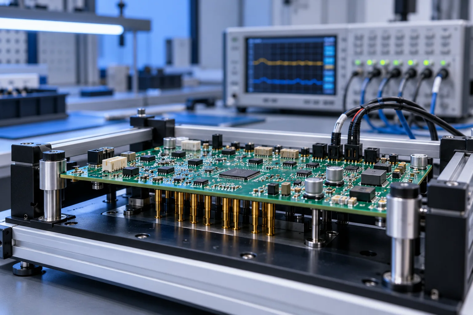
Functional testing powers and exercises the assembly according to an approved procedure. It might check startup, current consumption, power rails, digital interfaces, sensor response or outputs under a specified load. The combination should reflect what the actual product must do. NI’s electronics functional-test overview describes test systems built around the needs of different PCBA designs.
A released procedure should specify supply settings, power sequencing, firmware and configuration, input stimuli, connected loads, measurement points, limits, timing and pass/fail logic. Define safe connection and shutdown steps. If a communications interface is important, describe the transaction and expected response rather than simply asking whether the board turns on.
Agree ownership of fixtures, software, golden samples and updates. A reference sample can help validate setup, but it does not replace written limits. A fixture that produces intermittent contact failures needs maintenance and diagnosis; repeated testing until a board happens to pass can conceal a real problem.
Keep production functional test separate from design qualification, environmental reliability assessment and regulatory compliance. A short room-temperature check does not establish performance across every operating condition. Additional requirements must be specified and reviewed separately.
Build a Coverage Matrix for Prototype and Production
Choose checks from product risk, board design and build volume. For a prototype, engineering may prioritize diagnostic access and rapid feedback. A stable repeat build may justify a dedicated fixture and controlled automated sequence. Volume affects economics, but it does not decide which failures are acceptable.
Create a coverage matrix with one row for each critical characteristic: risk or failure mode, inspection or test method, required access, acceptance limit, sample rule, recorded result and responsible owner. Include a column for exclusions. This makes gaps visible before a purchase order assumes they are covered.
For example, a controller with a BGA and an external communications port could require hidden-joint inspection on specified connections, electrical checks of accessible power networks, and a functional communications transaction. These are complementary checks, not interchangeable guarantees. A different board may need a different combination.
XinshunPCB’s SMT inspection and test capabilities list process and test options for review. Confirm the actual combination, access requirements and fixture needs against your files. Keep the test revision aligned with the PCB, BOM and firmware; our BOM and AVL review checklist explains the material and revision controls that support that release.
Test Costs, Traceability and Failure Handling
Ask for separate prices for test development, fixture fabrication, programming setup and recurring execution. Cycle time, connections, operator work, report detail, maintenance and engineering changes can affect cost. Quote prototype, pilot and repeat volumes against the same coverage so that a lower unit price does not hide a reduced test scope.
Your turnkey or consigned assembly model determines sourcing responsibility, but test ownership still needs an explicit agreement. State who supplies firmware, tools, customer equipment and approval samples, and who approves program changes.
Define the records before production. Depending on the project, these may include board serial or lot identifier, design revision, test program and firmware version, timestamp, measured results and disposition. Agree retention and delivery format. Lot-level evidence is not automatically equivalent to a result linked to each serial number.
Plan failures as carefully as passes. Specify quarantine, analysis, authorized repair, retest steps and final approval. Distinguish a fixture contact issue from a product fault and record the reason for retest. An engineering change may require revised limits, fixture updates and revalidation; do not silently reuse an old program on a changed board.
RFQ Checklist for PCBA Testing Services
Send the supplier a controlled test package alongside the assembly files. This checklist helps procurement, quality and engineering compare the same deliverable:
- Build identity: PCB, BOM, placement, assembly drawing, firmware and variant revisions.
- Critical requirements: functions, risks, interfaces, workmanship standard and customer limits.
- Inspection scope: AOI stage, selected X-ray packages or joints, sampling and acceptance rules.
- Electrical access: schematics, netlist, test-point map, fixture constraints and permitted methods.
- Functional procedure: supplies, sequencing, loads, stimuli, communications, timing and pass/fail limits.
- Ownership and cost: fixture, software, approval sample, NRE, recurring test time and change responsibility.
- Release evidence: required records, failure disposition, repair authorization and retest policy.
Ask the assembler to return a written test scope with open decisions and exclusions. “AOI included” and “fully tested” are not sufficiently detailed descriptions for a controlled B2B build.
To discuss a PCBA quote with a defined test scope, send XinshunPCB your assembly package, expected quantities and available test instructions. We can review which inspection and testing options fit the design and identify the customer inputs required before production release.