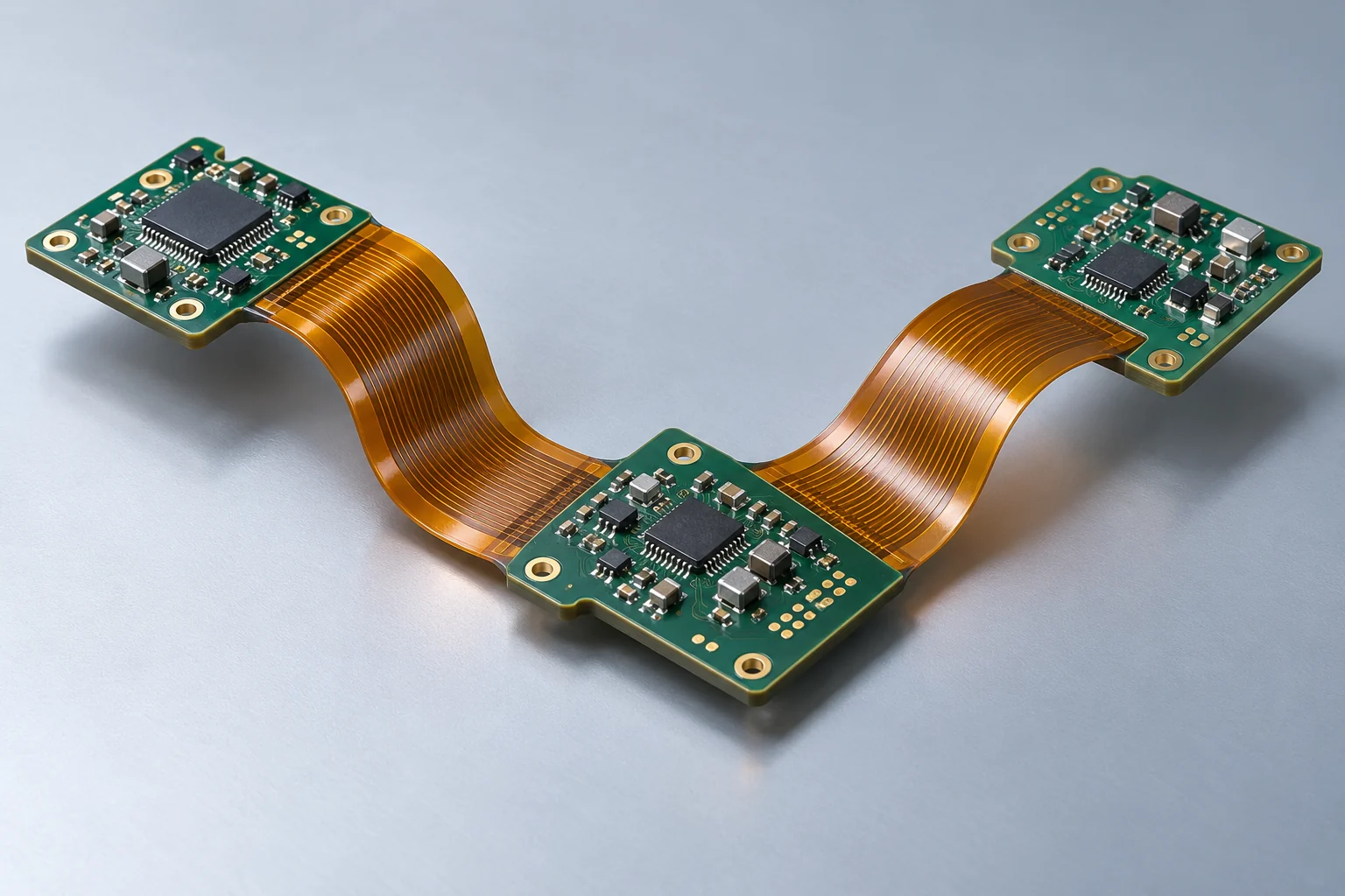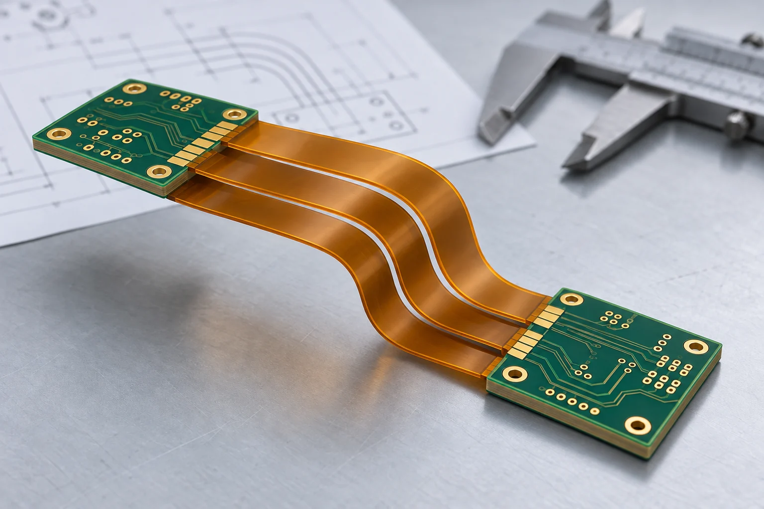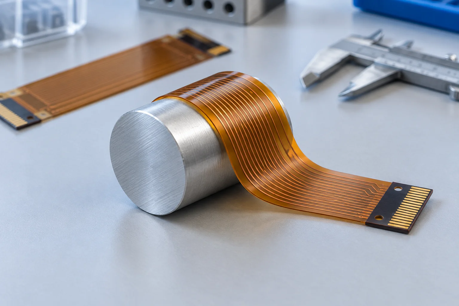

Why the Rigid-to-Flex Transition Needs Its Own Review
Rigid-flex PCB reliability depends on how the flexible circuit leaves the rigid section, how the assembly supports that junction and how the finished construction is verified. Define the transition boundary, keep the intended bending region clear of vulnerable features, and agree the layer terminations and acceptance plan with the fabricator before releasing artwork.
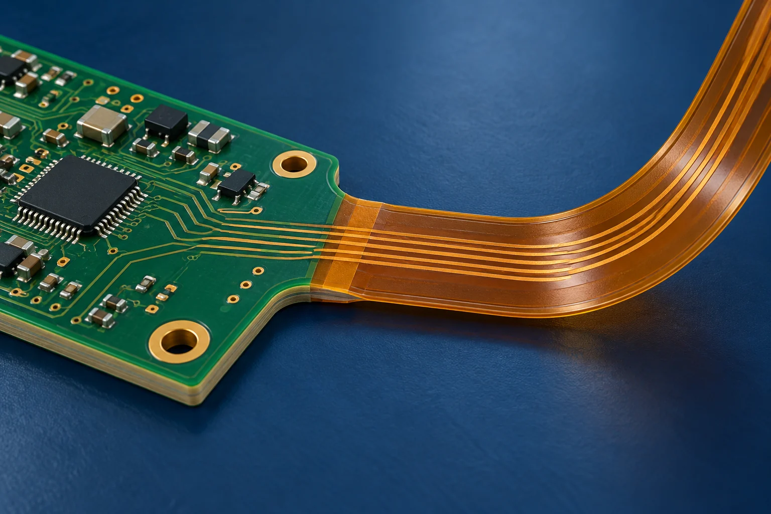
For B2B teams sourcing custom rigid-flex PCB manufacturing, a passing bare-board electrical test is only one part of that review. It confirms the tested connectivity at that time. It does not establish that the installed assembly will survive its specified motion, thermal exposure or handling.
Use this guide to turn a transition detail into a reviewable drawing and RFQ. The broader rigid-flex PCB design guidelines cover the full design release; this article focuses on the junction between rigid and flexible regions.
Mark the Transition, Bend Region and Support Points
Create one mechanical definition showing the rigid outline, the nominal rigid-to-flex boundary, the intended bend region and the installed positions of the rigid islands. Include datums and tolerances. A fold line alone leaves the fabricator and assembly team to infer where deformation is allowed.
For example, a flex arm may fit the enclosure when its boards are loose but become taut after both boards are screwed down. Review the worst permitted mounting positions and the installation sequence together. Record where the operator can hold the assembly, which surfaces may contact the flex and whether servicing requires another fold.
Use the flex PCB bend radius design guide to prepare the geometry inputs. State whether the board bends only during installation, moves during servicing or flexes repeatedly in operation. Ask the supplier to assess the proposed radius against the finished flex construction and duty.
Agree the straight region, if required, between the rigid edge and the start of the designed bend. Check that the assembly fixture and enclosure preserve it. Do not force a tight crease at the rigid edge to compensate for an undersized flex span.
Route Conductors and Place Features Around the Boundary
Würth Elektronik’s flex design guide recommends conductors crossing the rigid-to-flex boundary at right angles, smooth contours and no vias, pads or abrupt conductor changes in the bending region. Its guidance also calls for construction-specific distances between the transition and rigid-area features.
In the layout review, identify traces that turn, neck down, join a pad or change layer close to the junction. Move those features into an approved rigid region where possible. Mark any exception for explicit supplier review rather than hiding it in a general drawing note.
Treat a drilled hole, copper pad and coverlay opening as separate features with separate manufacturing tolerances. The nominal CAD clearance must leave room for the approved registration and outline tolerances. A visually clear screen view is not a tolerance analysis.
There is no universal via-to-transition number that fits every stackup. Even a single supplier’s construction-specific RIGID.flex design rules distinguish exposed copper, drill pads and protective-layer options. Obtain XinshunPCB’s applicable DFM values for the proposed build instead of copying another construction’s dimensions.
Coordinate Coverlay, Adhesive and Optional Strain Relief
Show where the coverlay, its adhesive and any bondply terminate relative to the rigid boundary. Include which flex layers continue through each rigid island. Review this detail with the regional stackup, not as a drawing added after routing is complete.
All Flex Solutions’ rigid-flex DFM guide explains cutback coverlay and bondply as a way to limit high-expansion adhesive in the rigid via region. It also describes optional beading at the interface to reduce local stress from handling or vibration. These are construction choices requiring review, not automatic additions to every rigid-flex board.
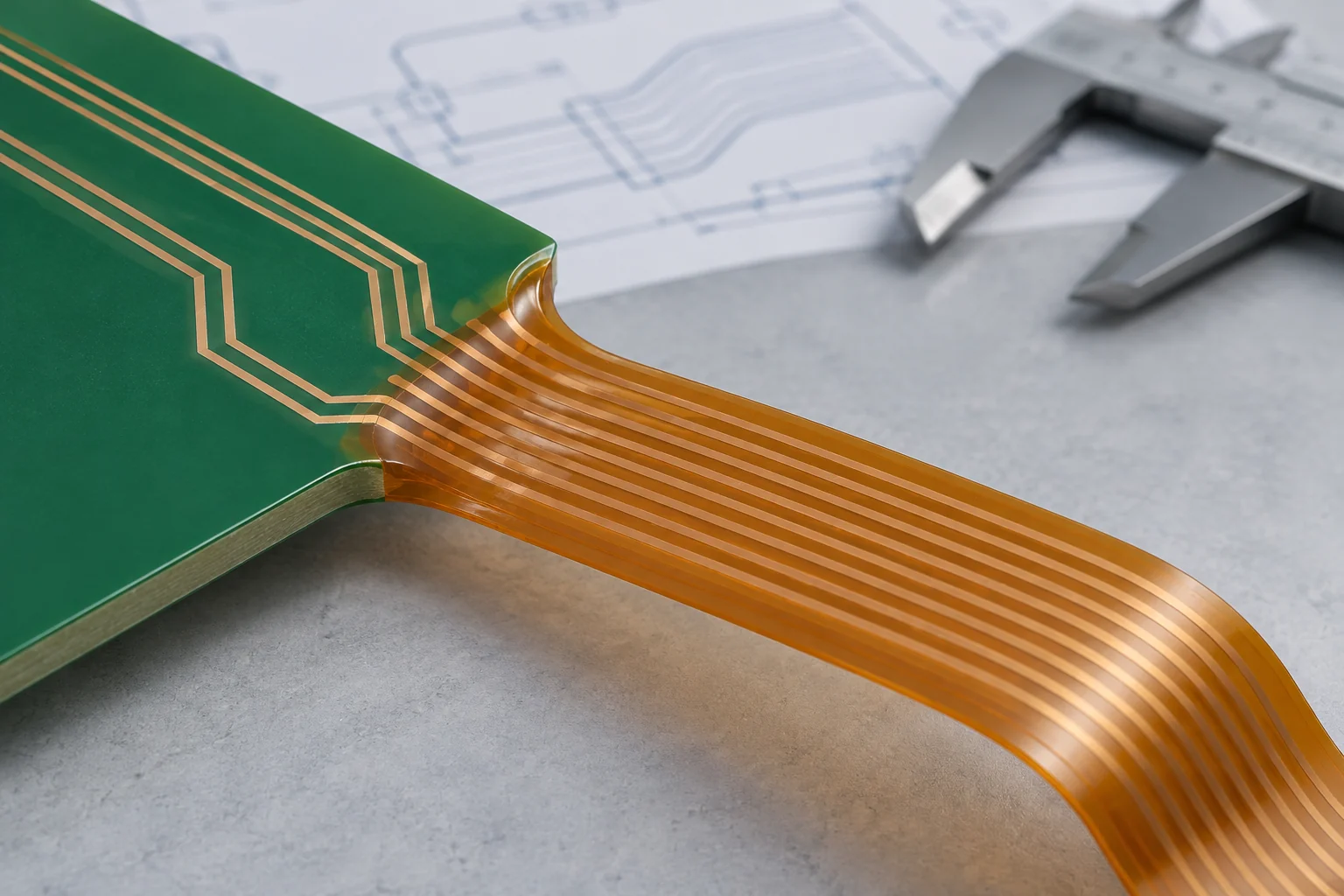
Use the coverlay versus solder mask guide when specifying the protective system. Identify the required material and openings, then ask the fabricator to confirm the overlap, cutback and resin-control detail appropriate to that system.
If a strain-relief fillet is proposed, put its material, location, permitted envelope and inspection expectations on the approved drawing. Check that it leaves the intended free span available and does not obstruct a connector, fastening point or inspection area. Do not treat the illustrative fillet in the image as a production specification.
Review Copper References and the Installed Flex Shape
Follow critical signals across the entire transition. Record the signal layer, reference conductor and any reference change between rigid and flex regions. Review impedance for both regional constructions, and ask how the proposed coupon represents the relevant geometry. An impedance target without an agreed stackup leaves an important assumption unresolved.
Balance electrical reference requirements with the mechanical construction. If a copper plane, shielding layer or protective film changes, send the revised stackup back through both electrical and mechanical review. Treat a hatched reference as a design decision requiring assessment, not a default cure for a difficult bend.
For separated flex groups, use the bookbinding and air-gap rigid-flex construction guide to define the unbonded boundaries and relative lengths. The transition review must still check how each group leaves the rigid island and settles into its installed path.
For recurring motion, add the operating envelope, travel, rate, temperature and required life to the static and dynamic flex supplier review. Installation success cannot substitute for qualification under the intended operating conditions.
Match Each Reliability Risk to Verification Evidence
Use the following review matrix to agree evidence before prototype ordering. It is a planning aid for the buyer, designer and supplier. The required tests, sampling, fixtures and acceptance limits must be selected for the application and included in the agreed scope.
| Risk to review | Evidence to request | Release question |
|---|---|---|
| Local copper strain at the junction | Approved bend definition, support arrangement and representative formed assembly | Does the real fixture preserve the reviewed geometry? |
| Material or adhesive termination near rigid vias | Regional stackup and agreed construction inspection records | Does the delivered build match the approved transition detail? |
| Electrical discontinuity or unstable connection | Bare-board test scope and continuity monitoring where motion testing requires it | Are the relevant nets checked during the specified exposure? |
| Damage during handling or assembly | Documented forming sequence and inspection before and after assembly | Can the assembly team reproduce the approved method? |
| Thermal, humidity or vibration exposure | Application-specific qualification plan and traceable results | Were the limits, sample basis and acceptance criteria agreed? |
Separate prototype qualification from routine production acceptance. A prototype test result applies to the tested construction and conditions. Keep a record of the board revision, stackup, manufacturing lot, assembly process and fixture used so later changes can be assessed against that evidence.
If a problem appears, preserve the failed assembly and its installation history before changing several design variables. Record whether the fault appears flat, formed, heated or moving. That distinction helps the teams decide what to inspect and what the next controlled experiment should change.
Prepare a Transition-Focused B2B RFQ and Release Checklist
Check the published rigid-flex PCB manufacturing capabilities against the proposed build, then submit a controlled revision for project-specific review. Ask the quotation to separate fabrication, forming aids, assembly support and qualification work so supplier offers cover comparable scope.
| RFQ item | Information to include |
|---|---|
| Construction | Rigid and flex layer order, materials, finished thicknesses, copper and protective layers |
| Transition detail | Rigid boundary, permitted terminations, feature clearances and optional fillet envelope |
| Mechanical duty | Flat and installed drawings, bend region, support points, motion and environment |
| Electrical requirements | Critical nets, references, impedance targets, tolerances and agreed test method |
| Acceptance and traceability | Applicable requirements, inspection records, qualification scope and revision control |
Use the PCB quotation file checklist to assemble artwork, drill data and fabrication notes. Mark unresolved transition details as questions. Request written closure or an approved supplier proposal before those assumptions become production instructions.
Before release, reconcile the mechanical model, fabrication drawing, stackup and artwork revision. Confirm that proposed DFM changes have been reviewed by the responsible electrical and mechanical owners. Retain the approved files with the purchase order and record which changes require another review.
Request a Rigid-Flex Transition Manufacturing Review
A useful transition review ends with an agreed construction, a reproducible installation method and evidence requirements that match the application. The purchasing team can then compare quotations without relying on a general reliability claim or an unexplained bend-radius value.
Send XinshunPCB your stackup, artwork, installed geometry, quantities and acceptance requirements to request a rigid-flex PCB transition and manufacturing review. Include any proposed coverlay cutback, strain-relief fillet or motion test so the manufacturing and verification scope can be discussed before ordering.
Technical references linked above are supplier design resources, not XinshunPCB process limits or substitutes for the applicable purchased standards and approved project documentation.
Rigid-Flex PCB Transition and Reliability FAQs
Practical answers about transition geometry, feature clearances, strain relief and verification before fabrication.
Rigid-Flex PCB Examples for Your Transition Review
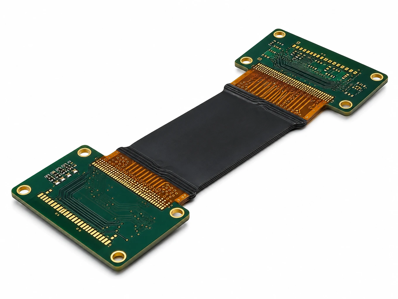
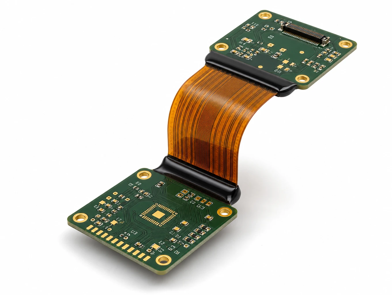
Use these product examples to discuss construction requirements. Dimensions, materials and acceptance scope require project-specific confirmation.

Continue Your Rigid-Flex PCB Design Review
Connect the transition detail with regional stackups, bend planning and multi-group flex construction.