
What Metal Core PCB Thermal Conductivity Really Tells You
Metal core PCB thermal conductivity describes how readily a specified material conducts heat. It does not, on its own, tell you the temperature of an LED, transistor or finished assembly. For a useful buying decision, identify which layer the quoted value describes, its thickness, the heat-transfer area and the path from the component to the surrounding air.
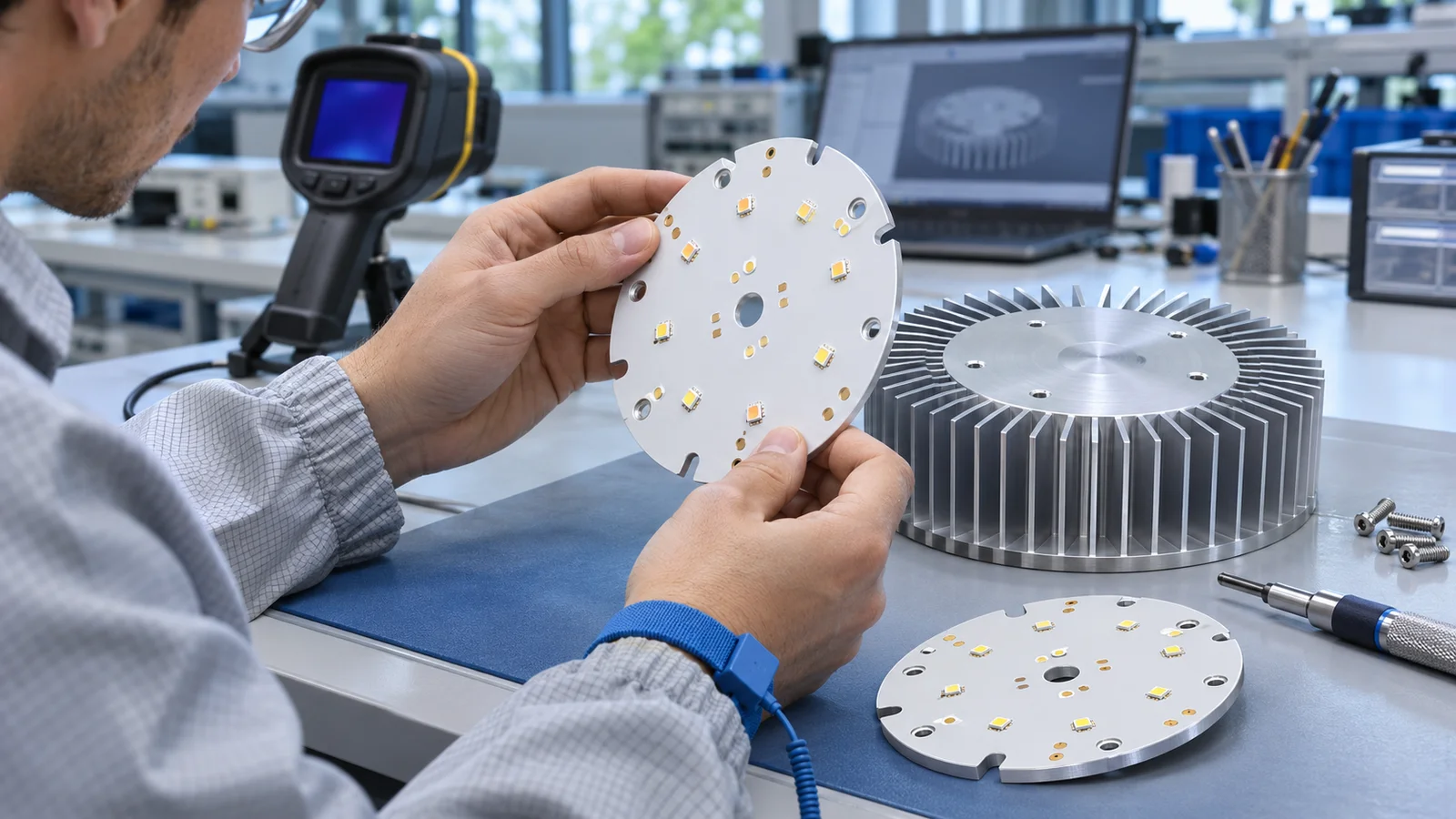
A material with a larger conductivity number can reduce resistance in one part of the construction. That benefit may be small if a thick interface pad, poor contact or an undersized heatsink dominates the assembly. Start with your heat source and temperature limits, then compare an approved construction rather than a headline rating.
Use XinshunPCB's metal-core PCB manufacturing range as the commercial starting point for aluminum-base, copper-base and other project-specific constructions. This guide supports that discussion with seven checks for engineers, buyers and supplier-quality teams.
Key takeaways
- Separate dielectric conductivity from metal-base and laminate values.
- Compare conductivity, thickness, area and test conditions together.
- Keep electrical isolation and mounting requirements in the specification.
- Validate operating temperature in the intended assembly before production approval.
Check 1: Identify the Complete Heat Path
A conventional insulated metal substrate transfers heat through several connected layers: the component attachment, circuit copper, insulating dielectric, metal base and the external mounting interface. The heatsink or enclosure then transfers heat to the environment. Each part can limit performance, and heat can also leave through parallel paths.
TCLAD describes IMS construction as copper circuitry, a dielectric that electrically insulates and bonds the layers, and an aluminum or copper base that spreads heat. That construction explains why a metal-core board can combine electrical isolation with a useful thermal path. It also explains why the conductivity of the base is not the conductivity of the dielectric.
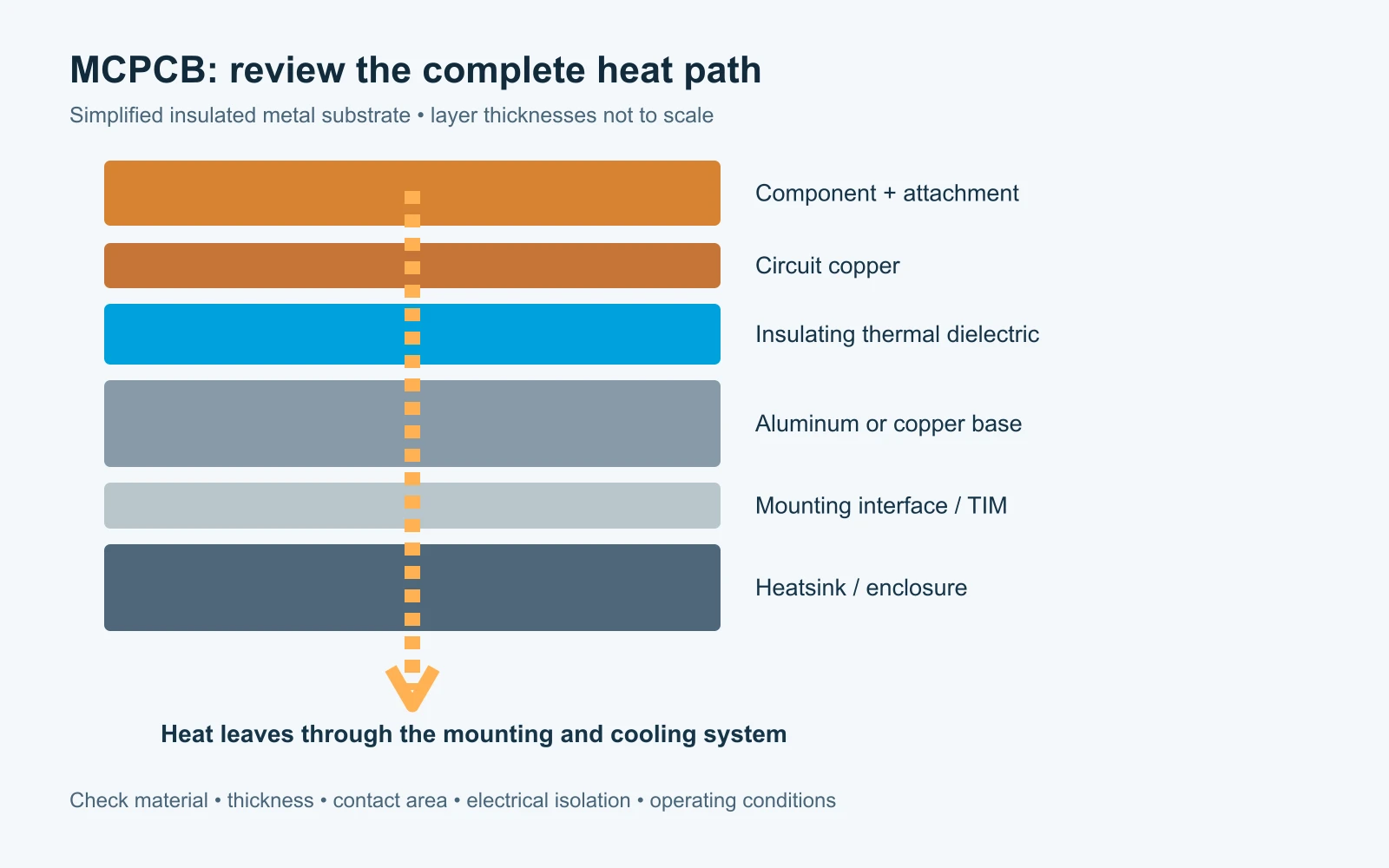
Draw the intended contact surfaces before choosing the material. Is the component's thermal pad electrically live? Does heat reach the base under the pad, spread laterally first, or cross additional circuit layers? Where is the board clamped, and which surface contacts the enclosure? A single-layer aluminum circuit board and a multilayer hybrid board need different reviews.
For a direct thermal-pad construction, a compatible package may contact a dedicated metal region without the same dielectric path underneath it. Treat this as a different electrical and thermal architecture. Do not apply an insulated-board calculation to every pad simply because both products are called MCPCBs.
Check 2: Compare Conductivity, Resistance and Units
Conductivity, thermal resistance and area-normalized thermal resistance answer different questions. A conductivity value belongs to a material under stated measurement conditions. Resistance describes a particular heat path. An area-normalized value helps compare interfaces, provided the measured construction and conditions are comparable.
| Quantity | Common unit | What to confirm |
|---|---|---|
| Thermal conductivity, k | W/(m·K) | Material, direction, temperature and test method |
| Thermal resistance, R | K/W or °C/W | Thickness, area, interfaces and test assembly |
| Area-normalized resistance, R × A | K·cm²/W or °C·cm²/W | Area convention, contact pressure and included layers |
For an ideal, uniform layer with one-dimensional steady conduction, R = t / (k × A). Here t is thickness in metres and A is area in square metres. This simplified relation is useful for screening a layer; it excludes contact resistance, lateral spreading and package details.
Consider an illustrative 100 mm² transfer area. A 100 µm dielectric at 2 W/(m·K) gives an ideal layer resistance of 0.50 K/W. Reducing that thickness to 75 µm gives 0.375 K/W. Keeping 100 µm and increasing conductivity to 3 W/(m·K) gives approximately 0.333 K/W. These are calculated examples, not material datasheet values or XinshunPCB performance guarantees.
At 5 W passing through that ideal layer, the corresponding temperature differences would be 2.50°C, 1.875°C and about 1.67°C. The improvement from the first to the third case is therefore about 0.83°C across that layer alone. The complete assembly may behave differently because its effective area and other resistances are different.
Check units before comparing two quotations. K·cm²/W is not interchangeable with K/W without an area conversion. Also ask whether a reported impedance is a steady-state result or depends on time and a specified test arrangement.
Check 3: Ask What the Conductivity Number Includes
A fair metal core PCB thermal conductivity comparison uses matching definitions. A value for the dielectric alone, a measured laminate stack and the bare aluminum or copper base can all be legitimate data, but they cannot be ranked as though they describe the same material.
The Bergquist Thermal Clad selection guide explains why thickness, interfaces and test method matter when comparing thermal data. Use that guidance to request the exact material designation and the relevant measurement conditions. A higher number produced by a different sample construction is not proof of a better board for your application.
- Identify the material grade and revision, rather than requesting only a generic W/m·K rating.
- Ask whether conductivity applies through the thickness or in the plane.
- Confirm the test method, sample construction and temperature.
- Request thermal resistance data for the proposed dielectric thickness when available.
- Record whether values are typical, specified limits or calculated estimates.
A purchasing description such as “high thermal conductivity PCB” leaves too much room for substitution. Specify the approved material and thickness, then define how an equivalent alternative would be reviewed. Supplier data should remain traceable to the material used for the production lot.
Keep component temperature limits separate from board-material ratings. A laminate temperature rating does not establish an LED junction temperature, and a successful bare-board inspection does not establish performance inside a sealed enclosure.
Check 4: Choose the Base and Copper for the Actual Design
Aluminum and copper bases are heat spreaders as well as structural parts. Select them using the heat-source geometry, mounting arrangement, weight and machining needs. Changing the base cannot automatically remove a bottleneck in the dielectric or in the board-to-heatsink interface.
An aluminum PCB can be a practical candidate when the thermal and mechanical review supports it. A copper-base construction may be useful for concentrated heat sources, but it changes weight, processing and cost. Ask the engineering team to compare the proposed stacks under the same boundary conditions instead of selecting a base solely from its bulk conductivity.
Circuit copper also matters. Larger copper areas can spread heat before it crosses the dielectric. Their usefulness depends on electrical connectivity, component placement and available layout space. The Texas Instruments PCB thermal calculator illustrates how package data, power dissipation and copper spreading area affect a temperature estimate. Its assumptions must be checked before applying a result to a different board construction.
Use the PCB copper thickness and heavy-copper guide when specifying circuit copper. Finished copper weight, metal-base thickness and total board thickness are separate requirements. Thicker circuit copper also affects etching, spacing, soldering and the mechanical stack.
For the available construction families and manufacturing discussion, review metal-core PCB engineering capabilities. Confirm the actual combination during quotation; a list of individual capabilities does not mean every combination is available in one board.
Check 5: Preserve Electrical Isolation and Mechanical Contact
Thermal improvements must preserve the required insulation system. A thinner dielectric may reduce one calculated resistance, but electrical withstand, operating voltage, spacing, processing and reliability still need review. A dielectric breakdown figure is not an automatic continuous working-voltage rating for the finished assembly.
Define the required test type, voltage, duration, leakage limit and the points between which it is applied. Specify creepage and clearance needs using the applicable end-product requirements. Pay particular attention to exposed metal at routed edges, mounting holes, countersinks and direct thermal pads.
| Design detail | Thermal or electrical question |
|---|---|
| Mounting holes and fasteners | Can the fastener contact a live region or distort the board? |
| Base flatness and surface condition | Will the intended interface make consistent contact? |
| Thermal interface material | What bond-line thickness, pressure and insulation are required? |
| Direct metal thermal pad | Is the component pad electrically compatible with the base? |
| Multilayer interconnects | How are conductors isolated from the metal base? |
Include the heatsink drawing or contact-area sketch in the review. State whether an interface pad, grease, adhesive or another mounting system is planned. Agree the assembly procedure and torque guidance with the responsible design team rather than using a universal fastener setting.
For power conversion and enclosure-level integration, the industrial and power electronics solution helps frame the wider project discussion. Application labels are starting points for engineering review, not evidence of a particular safety approval.
Check 6: Validate Temperature in a Representative Assembly
The acceptance question is whether the intended assembly stays within its approved temperature and electrical limits under the specified operating conditions. Material conductivity is one input. Agree the test setup before placing a production order so that buyer and supplier evaluate the same result.
- Define the load: identify the dissipated heat, duty cycle and simultaneous operating modes. Electrical input power is not always equal to heat dissipated in one device.
- Set the boundary conditions: record ambient temperature, enclosure, orientation, airflow, heatsink and interface material.
- Define measurement points: distinguish component case, board, base and heatsink temperatures. Use the component manufacturer's appropriate method to estimate junction temperature.
- Control the build: test the intended material, panel revision, soldering process and mounting arrangement.
- Record acceptance: agree limits, sample quantity and any thermal cycling or other qualification required by the application.
A thermal image is useful for finding hot regions, but surface emissivity, reflections and measurement setup affect the result. Compare repeatable measurements at defined locations; do not treat the color palette as a temperature specification. Prototype findings should be linked to the exact bill of materials and mechanical assembly.
Fabrication checks, electrical inspection and assembly testing serve different purposes. Use the PCBA testing and acceptance guide to separate inspection coverage from product-level thermal qualification. If the project includes assembly, agree the test fixtures and evidence as part of the scope.
Check 7: Compare the Cost of an Approved Construction
The lowest-risk price comparison is between quotations for the same approved construction and acceptance requirements. A premium dielectric or copper base is worthwhile when it solves a demonstrated need. Buying a higher conductivity grade without checking the bottleneck can add cost while changing little in the finished product.
Ask for a baseline quotation and a clearly identified engineering alternative when a tradeoff is useful. For example, the supplier can review a different dielectric grade, base thickness or panel arrangement. Each alternative should state its changed assumptions and require your approval before production. Do not compare a bare-board price with an assembled, tested and shipped unit price.
- Construction: layer count, metal base and alloy, base thickness, dielectric grade and thickness, finished copper, finish and mask.
- Thermal inputs: heat-source positions, power dissipation, temperature limits and available contact area.
- Electrical requirements: operating conditions, isolation tests, conductor spacing and any relevant product requirements.
- Mechanical details: outline, holes, flatness needs, mounting method, contact surfaces and panel restrictions.
- Commercial scope: prototype and production quantities, delivery destination, assembly, testing and required records.
- Change control: drawing revision, approved alternates and which changes require written review.
The PCB manufacturing cost guide explains why a meaningful quotation includes more than a material label. Repeatedly changing the material after tooling or qualification can outweigh an apparent unit-price saving. A stable specification helps suppliers quote consistently and helps buyers compare the actual deliverable.
Send a controlled file package using the PCB quotation file checklist. For this topic, include a material stack drawing and thermal or mounting requirements alongside the fabrication data. Request a review of missing assumptions before accepting a lower-priced substitute.
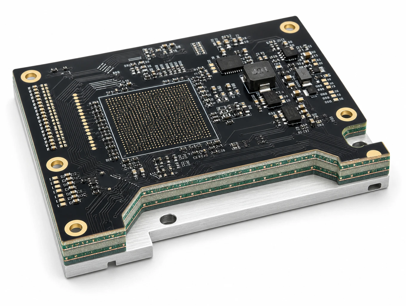
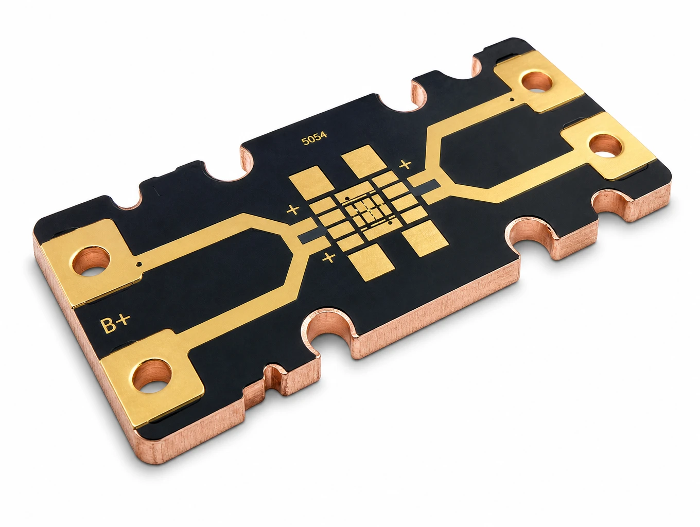
Metal-Core PCB Construction Examples for Engineering Review

Applications Where the Full Thermal Path Matters
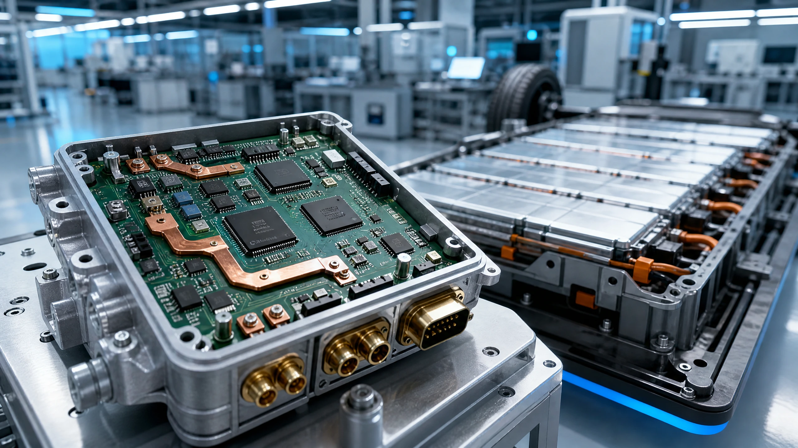
Automotive Electronic
Engineered to withstand extreme mechanical shock, high-voltage switching surges, and thermal cycling from –40°C to +150°C. XinshunPCB delivers IATF 16949-aligned, IPC-A-610 Class 3 turnkey PCB fabrication and SMT assembly for electric vehicle (EV) powertrains, ADAS sensing, high-voltage BMS, and under-hood body control modules.
Explore Solutions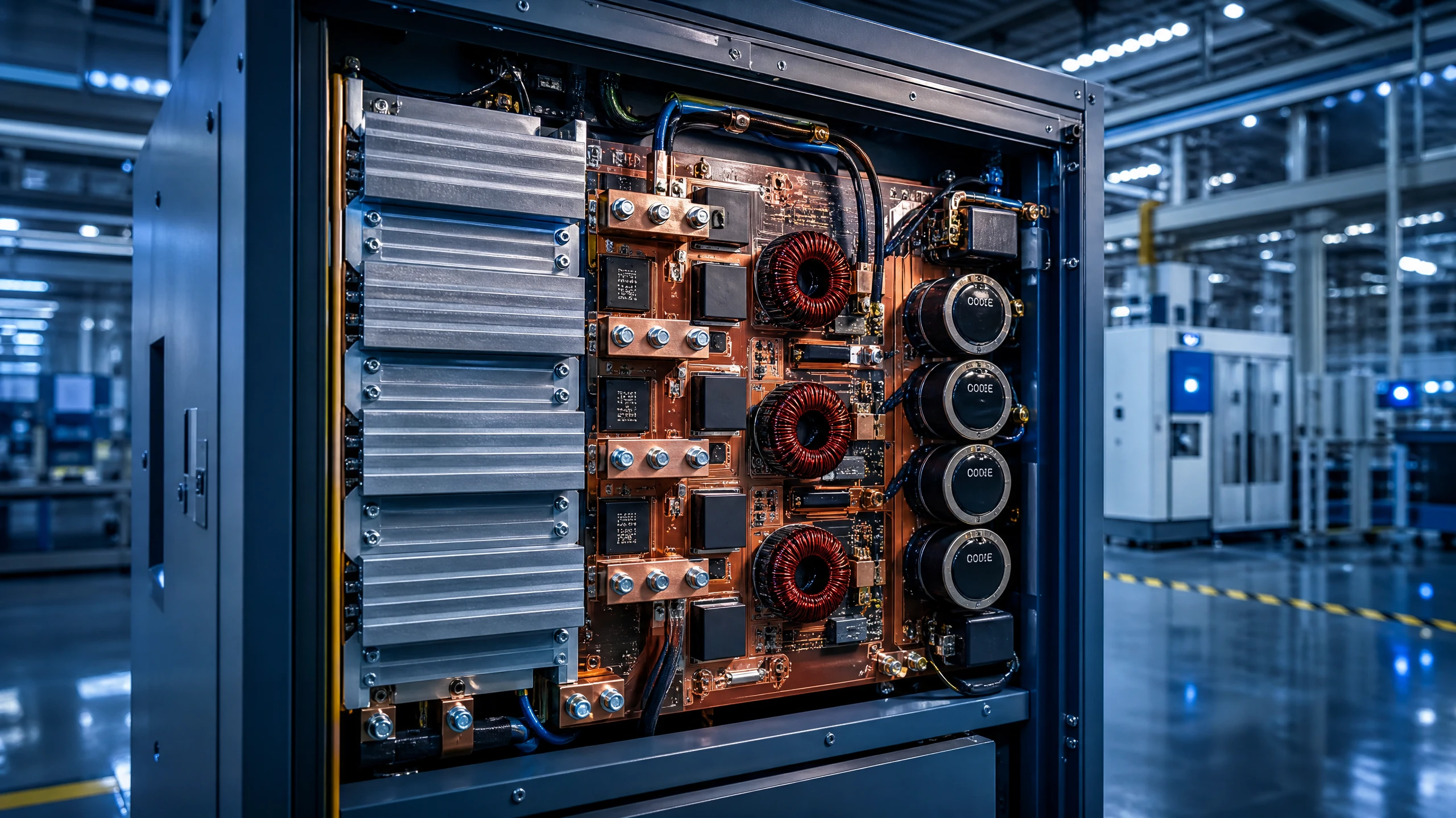
Industrial & Power Electronics
Engineered to withstand massive electrical currents, thermal stress, and continuous mechanical vibration. XinshunPCB delivers IPC Class 3 heavy copper boards, high-thermal metal-core solutions, and turnkey SMT assemblies for grid-scale energy storage, industrial robotics, motor drives, and solar inverters.
Explore Solutions
Telecommunications & IoT
From wireless gateways and connected sensors to networking equipment, XinshunPCB supports custom PCB fabrication and assembly for communication hardware. Align materials, stackups, compact layouts, and production testing with your application, from initial prototypes to repeat production.
Explore Solutions Automotive Electronic
Engineered to withstand extreme mechanical shock, high-voltage switching surges, and thermal cycling from –40°C to +150°C. XinshunPCB delivers IATF 16949-aligned, IPC-A-610 Class 3 turnkey PCB fabrication and SMT assembly for electric vehicle (EV) powertrains, ADAS sensing, high-voltage BMS, and under-hood body control modules.
Explore Solutions Industrial & Power Electronics
Engineered to withstand massive electrical currents, thermal stress, and continuous mechanical vibration. XinshunPCB delivers IPC Class 3 heavy copper boards, high-thermal metal-core solutions, and turnkey SMT assemblies for grid-scale energy storage, industrial robotics, motor drives, and solar inverters.
Explore Solutions Telecommunications & IoT
From wireless gateways and connected sensors to networking equipment, XinshunPCB supports custom PCB fabrication and assembly for communication hardware. Align materials, stackups, compact layouts, and production testing with your application, from initial prototypes to repeat production.
Explore SolutionsMetal Core PCB Thermal Conductivity FAQs
Request a Metal-Core PCB Thermal and Manufacturing Review
A useful metal core PCB thermal conductivity specification connects the material data to your actual heat path. Select the dielectric, circuit copper and base together, preserve isolation, and qualify the proposed mounting arrangement before releasing production.
Request a project-specific metal-core PCB quote with your fabrication files, proposed construction, quantities, heat-source information and mounting details. XinshunPCB can review the manufacturing scope and identify the material or assembly assumptions that need confirmation before a quotation is finalized.