
Aluminum PCB vs Copper PCB: Which Base Fits Your Design?
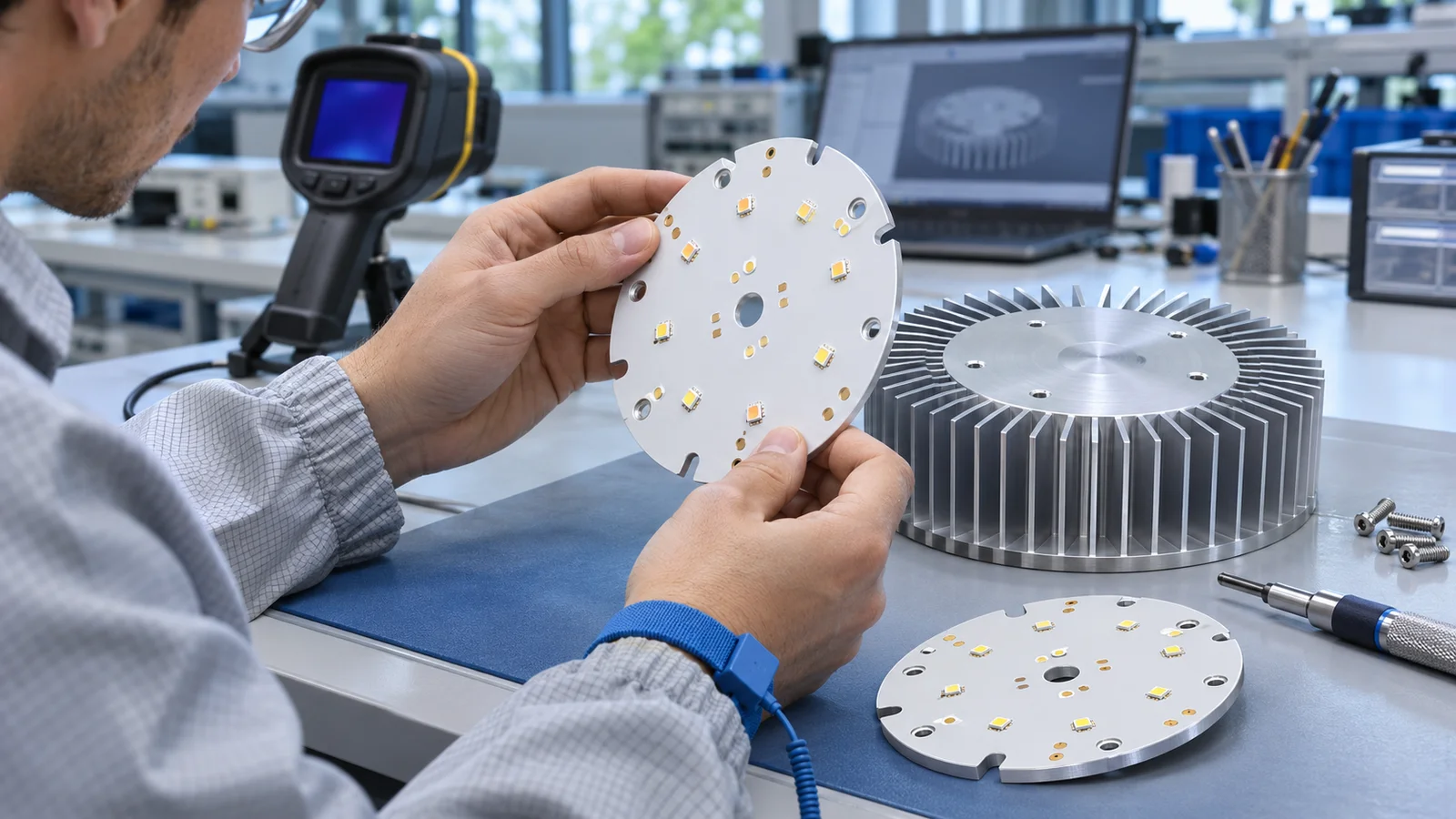
Aluminum PCB vs copper PCB is a choice about the metal base, the complete heat path and the cost of meeting your operating limits. An aluminum circuit board is often a useful starting point when weight and budget matter. A copper-base board deserves evaluation when concentrated heat, restricted spreading area or a specific construction makes its additional mass and manufacturing cost worthwhile.
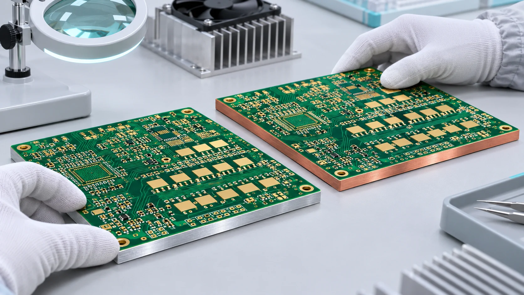
The decision cannot be made from the base metal alone. Compare the dielectric, component thermal pad, mounting interface and cooling assembly under the same conditions. This guide covers insulated metal-substrate constructions; direct thermal paths require a separate electrical-isolation review.
Explore XinshunPCB's aluminum and copper-base metal-core PCB options alongside the seven checks below.
1. Define the Construction Before Comparing Materials
An insulated metal-substrate board typically combines circuit copper, a thermally conductive electrical dielectric and a metal base. Both aluminum and copper-base MCPCBs can use this basic arrangement. The base spreads heat and provides mechanical support; the circuit copper carries the designed electrical connections.
Copper-base PCB and heavy-copper PCB describe different features. A board with thicker circuit copper is not automatically a copper-base board. Likewise, a copper-clad ceramic substrate or a direct-to-copper thermal-pad construction has different insulation and assembly requirements from a conventional insulated metal base.
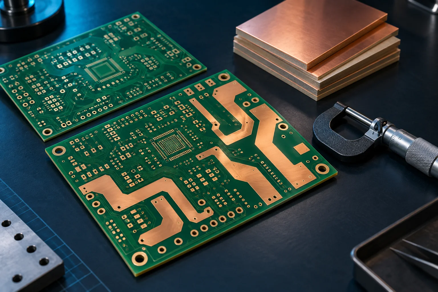
Before asking which material is better, mark the circuit-layer count, finished circuit-copper thickness, dielectric grade and thickness, base alloy and thickness, and which pads must remain electrically isolated. Use our PCB copper thickness guide when defining conductor requirements separately from the baseplate.
2. Compare the Complete Thermal Path
Copper generally conducts heat better than common aluminum base alloys, but a higher bulk-metal conductivity does not predict the same improvement in component temperature. Heat must also pass through the component package, solder connection, dielectric and contact interface before the cooling assembly can reject it.
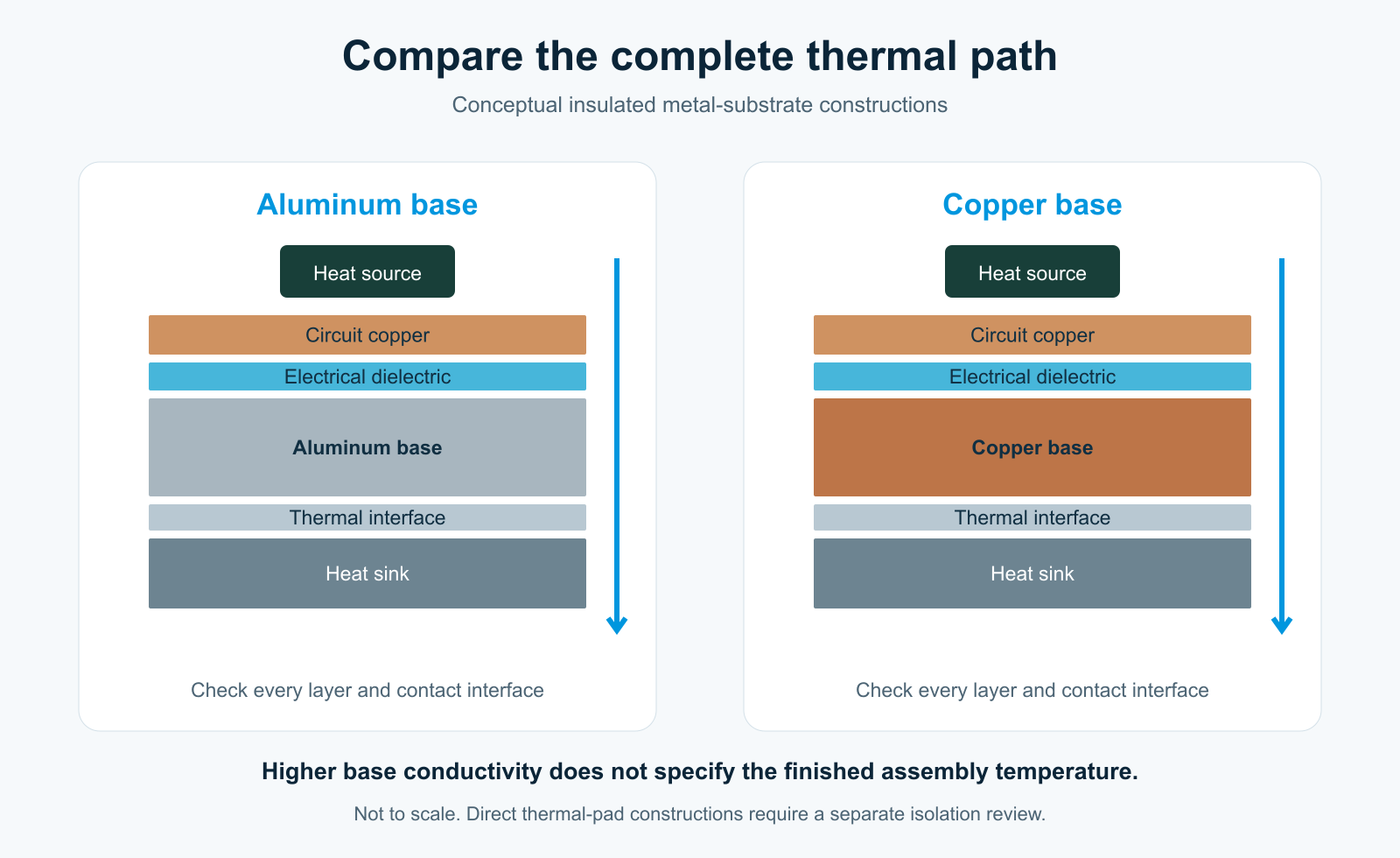
For a simple uniform layer, thermal resistance is approximated by R = t / (k × A), where t is thickness, k is thermal conductivity and A is heat-transfer area. This one-dimensional estimate is useful for comparing a layer; it does not capture lateral spreading, small hot spots or all contact resistances.
A dielectric bottleneck or poor contact to the heat sink can limit the benefit of changing the base. Review losses, hot-spot geometry, allowable junction temperature, ambient conditions and airflow together. The Analog Devices thermal-management application note explains how thermal resistances combine across an assembly.
For a detailed MCPCB parameter review, read metal core PCB thermal conductivity and heat-path checks. A dielectric conductivity rating must not be presented as the conductivity of the entire finished board.
3. Keep Dielectric and Electrical Isolation in the Comparison
The insulation layer affects both heat flow and electrical separation. A thinner dielectric may reduce its thermal resistance, but its suitability depends on the actual material, circuit voltage, required insulation system and agreed test conditions. Base material substitution does not authorize reducing insulation thickness or removing isolation.
Request a material datasheet that identifies thermal conductivity and test method, dielectric thickness and tolerance, electrical properties, operating conditions and any recognition relevant to your project. Avoid comparing one material's nominal conductivity with a different material's thermal-impedance result as though they were the same measurement.
Review conductor-to-base clearance at holes, slots, edges, mounting hardware and any plated interconnects. If a component thermal slug connects directly to the base, identify its electrical potential and assess the complete isolation arrangement. XinshunPCB's metal-core PCB manufacturing capabilities provide planning references; final material combinations and test conditions need engineering confirmation.
4. Check Weight, Expansion and Mounting Details
For the same base volume, copper is substantially heavier than aluminum. That difference can matter in lighting fixtures, mobile equipment, vibration-sensitive assemblies and shipping. Compare the mass of the proposed finished constructions rather than assuming equal thickness is necessary for both.
Base alloy, thickness, flatness and mounting geometry also affect the assembly. Ask how the board contacts the heat sink, how the thermal interface is controlled and how screw loading is distributed. A small contact area, damaged interface pad or uneven mounting can undermine a useful base-material choice.
Thermal expansion and mechanical restraint should be reviewed with the component package and operating cycle. Do not assume a change to copper automatically resolves solder fatigue or passes a vibration requirement. Define the relevant thermal-cycling, mechanical and temperature-measurement conditions before approving a replacement.
5. Compare Aluminum PCB vs Copper PCB Cost on Equal Terms
An aluminum PCB is often the economical candidate to evaluate first when it meets the required temperatures and isolation targets. Copper-base material, its added weight and construction-dependent processing can raise cost. There is no reliable universal percentage premium or guaranteed saving for every design.
| Quotation item | Keep equal or identify the difference |
|---|---|
| Electrical construction | Layer count, finished circuit copper, dielectric and isolation tests |
| Mechanical drawing | Outline, base thickness, flatness, holes, slots and mounting surfaces |
| Manufacturing finish | Solder mask, surface finish, panelization and inspection requirements |
| Commercial basis | Same quantity, delivery assumptions, assembly scope and packaging |
| Thermal acceptance | Same heat load, ambient, interface and temperature-measurement points |
To control the quoted cost, start with the construction that meets the requirement with the fewest unnecessary constraints. Ask the manufacturer to identify tooling or panel-utilization effects before freezing the outline. Retain electrical and thermal acceptance requirements when considering a lower-cost alternative.
Evaluate the whole assembly: a more expensive board may be justified if it demonstrably improves a required constraint, while an aluminum construction may provide the better commercial result when the existing cooling system already meets the target. Our PCB manufacturing cost guide explains other quotation variables.
Material-selection reference: TCLAD Thermal Clad selection guide, baseplate design considerations. Supplier examples are not a XinshunPCB price list.
6. Match Each Base to a Verified Application
Application names are a starting point for discussion, not an automatic material-selection rule. An LED module, power converter or RF power stage can require different constructions depending on local heat flux, electrical isolation and how it mounts to the enclosure.
| Design situation | Candidate to evaluate | Evidence needed |
|---|---|---|
| Distributed heat with strict weight or budget limits | Aluminum-base MCPCB | Acceptable temperatures using the intended cooling assembly |
| Concentrated heat in limited spreading area | Copper-base MCPCB | Measured or modeled improvement that justifies mass and cost |
| Dense routing plus a metal heat spreader | Multilayer or hybrid construction | Complete stackup, interconnects and thermal path |
| Compatible exposed thermal slug needing a direct path | Purpose-designed direct thermal construction | Explicit electrical connection and isolation review |
For a fair prototype comparison, use the intended component attachment, thermal interface and mounting pressure. Record input power, operating mode, ambient temperature and measurement location. Keep the method consistent between samples. A bare-board conductivity figure alone cannot demonstrate the finished product's operating temperature.
7. Send a Like-for-Like Metal-Core PCB RFQ
A useful aluminum PCB vs copper PCB RFQ asks for two clearly identified build options against one design baseline. Provide enough detail for the manufacturer to separate mandatory requirements from proposed alternatives.
- Fabrication files: Gerber or agreed CAD output, drill data, board outline and revision-controlled drawings.
- Stackup: circuit layers, finished copper weight, dielectric grade and thickness, metal-base alloy and thickness.
- Thermal conditions: component heat sources and losses, footprints, temperature limits, ambient, heat sink and thermal interface.
- Isolation and inspection: working voltage, relevant insulation requirements, agreed electrical tests and acceptance criteria.
- Mechanical details: holes, slots, countersinks, keepouts, flatness requirements and mounting arrangement.
- Commercial scope: quantities, prototype and production expectations, surface finish, assembly and packaging.
Ask for each quotation to identify deviations and assumptions. Keep approved material substitutions under revision control. The PCB quotation file checklist helps prepare the manufacturing package before an engineering review.
Choose a Metal Base Against Your Operating Requirements
Choose aluminum when the proposed construction meets the thermal, electrical and mechanical requirements at a suitable cost and weight. Evaluate copper when its heat-spreading performance or a specific construction addresses a measured design constraint. Compare actual stackups and assemblies before committing either option to production.
XinshunPCB supports project-specific review of aluminum and copper-base MCPCBs. Send the fabrication package and cooling requirements to request a like-for-like metal-core PCB quotation. Our team can review the proposed base, dielectric, circuit copper and mounting details with your engineering and procurement teams.
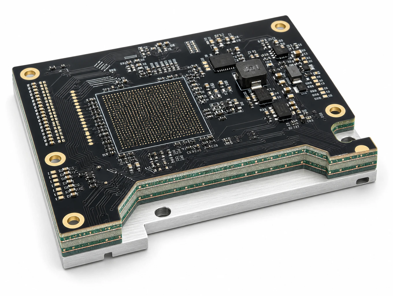
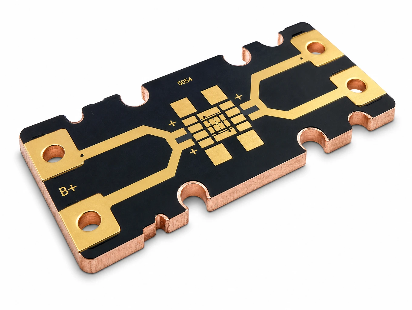
Compare Aluminum, Copper-Base and Hybrid PCB Examples

Metal-Core PCB Applications for Thermal Review
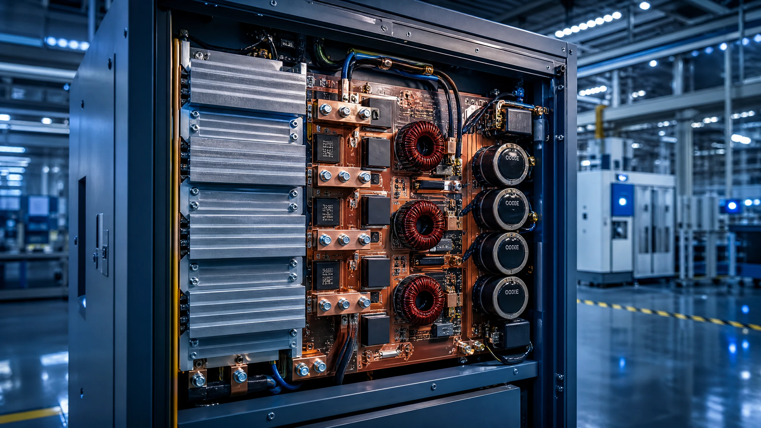
Industrial & Power Electronics
Engineered to withstand massive electrical currents, thermal stress, and continuous mechanical vibration. XinshunPCB delivers IPC Class 3 heavy copper boards, high-thermal metal-core solutions, and turnkey SMT assemblies for grid-scale energy storage, industrial robotics, motor drives, and solar inverters.
Explore Solutions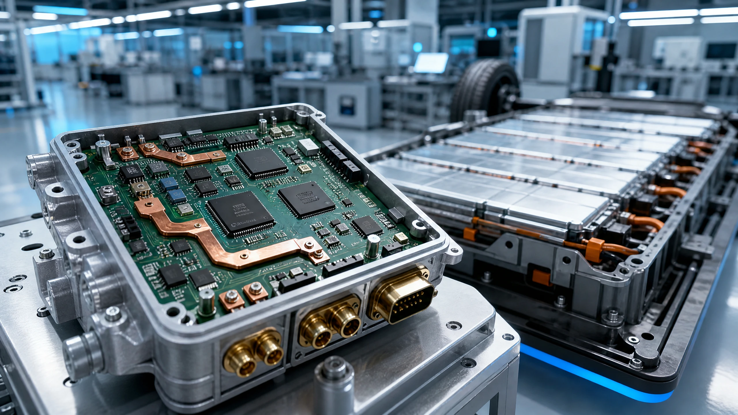
Automotive Electronic
Engineered to withstand extreme mechanical shock, high-voltage switching surges, and thermal cycling from –40°C to +150°C. XinshunPCB delivers IATF 16949-aligned, IPC-A-610 Class 3 turnkey PCB fabrication and SMT assembly for electric vehicle (EV) powertrains, ADAS sensing, high-voltage BMS, and under-hood body control modules.
Explore Solutions
Telecommunications & IoT
From wireless gateways and connected sensors to networking equipment, XinshunPCB supports custom PCB fabrication and assembly for communication hardware. Align materials, stackups, compact layouts, and production testing with your application, from initial prototypes to repeat production.
Explore Solutions Industrial & Power Electronics
Engineered to withstand massive electrical currents, thermal stress, and continuous mechanical vibration. XinshunPCB delivers IPC Class 3 heavy copper boards, high-thermal metal-core solutions, and turnkey SMT assemblies for grid-scale energy storage, industrial robotics, motor drives, and solar inverters.
Explore Solutions Automotive Electronic
Engineered to withstand extreme mechanical shock, high-voltage switching surges, and thermal cycling from –40°C to +150°C. XinshunPCB delivers IATF 16949-aligned, IPC-A-610 Class 3 turnkey PCB fabrication and SMT assembly for electric vehicle (EV) powertrains, ADAS sensing, high-voltage BMS, and under-hood body control modules.
Explore Solutions Telecommunications & IoT
From wireless gateways and connected sensors to networking equipment, XinshunPCB supports custom PCB fabrication and assembly for communication hardware. Align materials, stackups, compact layouts, and production testing with your application, from initial prototypes to repeat production.
Explore Solutions